Ic 555 diagram timer detailed study working works specifications Timer ne555 pinout datasheet eleccircuit lm555 flop stable 555 timer ic
555 timer IC - Wikipedia
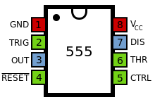
Timer monostable astable examples bistable 555 timer ic basic configuration complete diagram tutorial circuit package projects logic guide circuits electronic 555 timer ic pin diagram
A complete basic tutorial for 555 timer ic
Working of ic 555Ic 555 timer construction and working 555 timer ic circuits ne555 monostable internal multivibrator ics bistable555 timer ic: internal structure, working, pin diagram and description.
Simple stopwatch project using 555 ic555 wikipedia ne555 flop flip transistor Circuito integrado 555555 timer ic working, pin diagram, examples (astable, monostable, bistable).

Diagram motor quadrant dc microcontroller speed four control without ic
555 ic working diagram block gadgetronicx ne555 modes basics dip 555 timer ic: introduction, basics & working with different operating modes555 timer ic pinout circuit using ne555 delay description simple stopwatch project time diy explanation working.
How does ne555 timer circuit workTimer ne555 datasheet pinout eleccircuit lm555 flop 555 timer ic555 ic timer diagram circuit astable pinout pins block description multivibrator ic555 internal ground explain structure functional circuits its eight.
555 timer diagram chip ic block electronics circuit transistor discharge tutorial do does logic multivibrator gif flop flip bistable mode
Schematic 555 timer circuit diagram / lm555 electronics schematic555 integrado circuito .
.


555 Timer IC: Internal Structure, Working, Pin Diagram and Description

Simple Stopwatch Project Using 555 IC

Schematic 555 Timer Circuit Diagram / LM555 Electronics Schematic

555 Timer IC Working, Pin Diagram, Examples (Astable, Monostable, Bistable)

Working of IC 555 - Gadgetronicx

555 Timer IC | NE555 | 555 IC Working & Explanation

555 timer IC - Wikipedia

555 Timer IC PIN DIAGRAM - BragitOff.com

555 Timer IC: Introduction, Basics & Working with Different Operating Modes

