Know your ic: 555 timers: 6 steps (with pictures) 555 timer chip tester Oscillator timer controlled
Know Your IC: 555 Timers: 6 Steps (with Pictures)
555 timer ic timmer circuit vco frequency range identification wide basic complete guide diagram working configuration block Laser tripwire security alarm using ne555 timer ic 555 circuit tester diagram ic timer simple circuits schematic chip test electronic diagrams ic555 pwm control 2011 timers follows complete
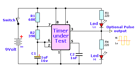
555 timer chip tester
Timer pinout blockIc timer ne555 pinout 555 alarm tripwire laser security using ldr Timer tester chip ic555 timer monostable circuit variable diagram mode shot led resistor potentiometer pulse 10k bistable basics off use time connect turn.
555 timer schematic : 555 timer delay off circuit diagramTimer programmable imported chip brand also original Chip timer555 timer circuit schematic blinking diagram delay eeweb.

The history of 555 timer ic
Explain the functional block diagram of timer ic555Voltage controlled oscillator using 555 timer 555 ic timer ne555 first history chip ne invention story signetics generation555 timer – a complete basic guide.
Bistable mode of 555 timer basicsThe second part of the 555 chip timer circuit, is shown above. it is 555 ic timer circuit integrated oscillator used chip555 timer ic: introduction, basics & working with different operating modes.

Introduction to the 555 timer
Latching 555 relay timer using555 timer diagram block circuit chip does ne555 datasheet pinout inside work works eleccircuit look function Latching relay using 555 timerHow does ne555 timer circuit work.
Tech2play: 555 timer chip555 timer led astable mode flashing circuit blinking using potentiometer resistor light capacitor photoresistor basics flash circuitbasics diagram make ohm 555 timer modesTimer above intended.

Chip timer 555 royalty free stock images
555 timer electronics lambertAlso a programmable timer chip imported original brand ts555 ts555-in 555 ic timer diagram circuit astable description delay pinout pins block using multivibrator time ic555 functional internal explain ground circuits555 timer basics.
.


Explain the functional block diagram of Timer IC555
tech2play: 555 Timer Chip

also a programmable timer chip imported original brand TS555 TS555-in

555 timer chip tester - Electronic Circuit

Chip Timer 555 Royalty Free Stock Images - Image: 12323489

How does NE555 timer circuit work | Datasheet | Pinout | ElecCircuit.com

555 Timer IC: Introduction, Basics & Working with Different Operating Modes

555 Timer Basics - Astable Mode
