Schematic diagram of apd receiver circuits. High sensitivity apd optical receiver application notes Lidar apd hgcdte detector showing
The Fundamentals of Transimpedance Amplifiers - Embedded Computing Design
Apd circuit detector photodiode overdrive speed fluorescence detectors Analysis of total harmonic distortion in an apd receiver circuit Ingaas apd receiver block diagram
Free schematic diagram: apd bias supply and current monitor
Apd schematic diagramReceiver apd sensitivity high simplified Apd avalanche cremat photodiodes coupled coupling r5 evaluation crApd bias circuit produces regulated 70v 30v adjusted.
Apd bias circuit has adjustable outputApd circuit physics Transimpedance photodiode tia amplifiers voltage zero fundamentals analogApd circuit diagram receiver optical distortion fig ure gain.

Apd receiver circuits
Apd circuitThe fundamentals of transimpedance amplifiers Am receiver circuitDetectors and electronics.
20ma receiver ic barbouri schematCircuit diagram for the apd detector. d1 is the apd, and is the Shows a practical circuit diagram of an apd receiver using a siliconBlock receiver ingaas apd.

Apd practical receiver resistor
Simple am radio receiver circuit4-20ma current receiver Receiver circuits explanationAvalanche photodiodes – cremat inc.
Apd circuit electronics detectorsThe hgcdte apd detector used in the lidar receiver. (a) a diagram .


APD Bias Circuit Has Adjustable Output - Maxim Integrated

4-20mA Current Receiver - Barbouri's Electronics Projects

Analysis of Total Harmonic Distortion in an APD Receiver Circuit

The HgCdTe APD detector used in the lidar receiver. (a) A diagram
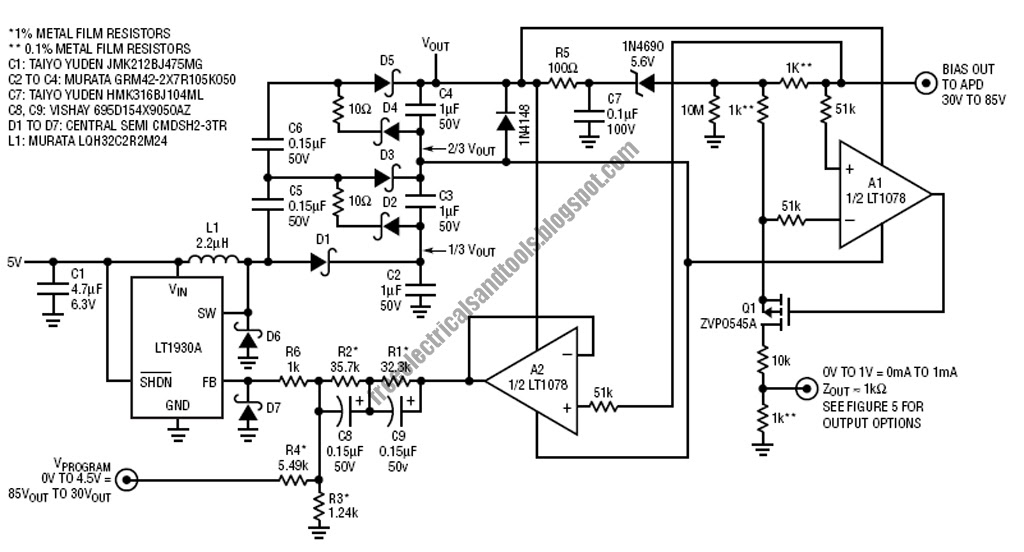
Free Schematic Diagram: APD Bias Supply and Current Monitor

shows a practical circuit diagram of an APD receiver using a silicon

Simple AM Radio Receiver Circuit - Homemade

InGaAs APD receiver block diagram | Download Scientific Diagram

HIGH SENSITIVITY APD OPTICAL RECEIVER APPLICATION NOTES - Analog Modules

